.png)
Am Radio Circuit Diagram
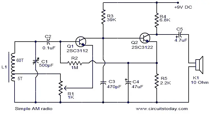
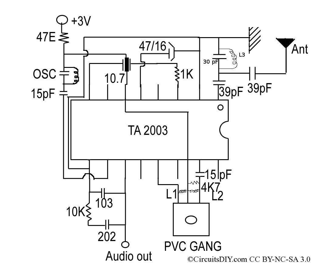
The circuit in the figure below is an integrated circuit am radio containing all the active radio frequency circuitry within a single ic. The circuit is using only few components to make a good quality am receiver.
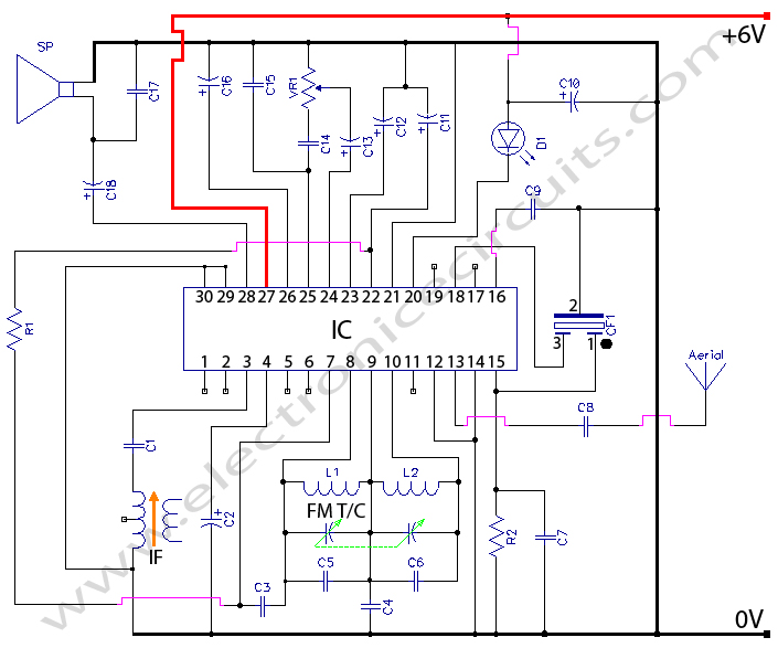
The circuit is designed around the ic zn414z which is a ten transistor tuned radio read more.

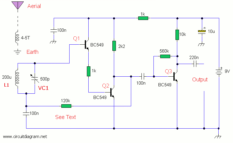
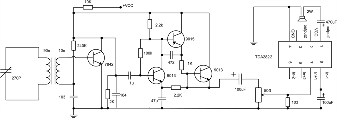
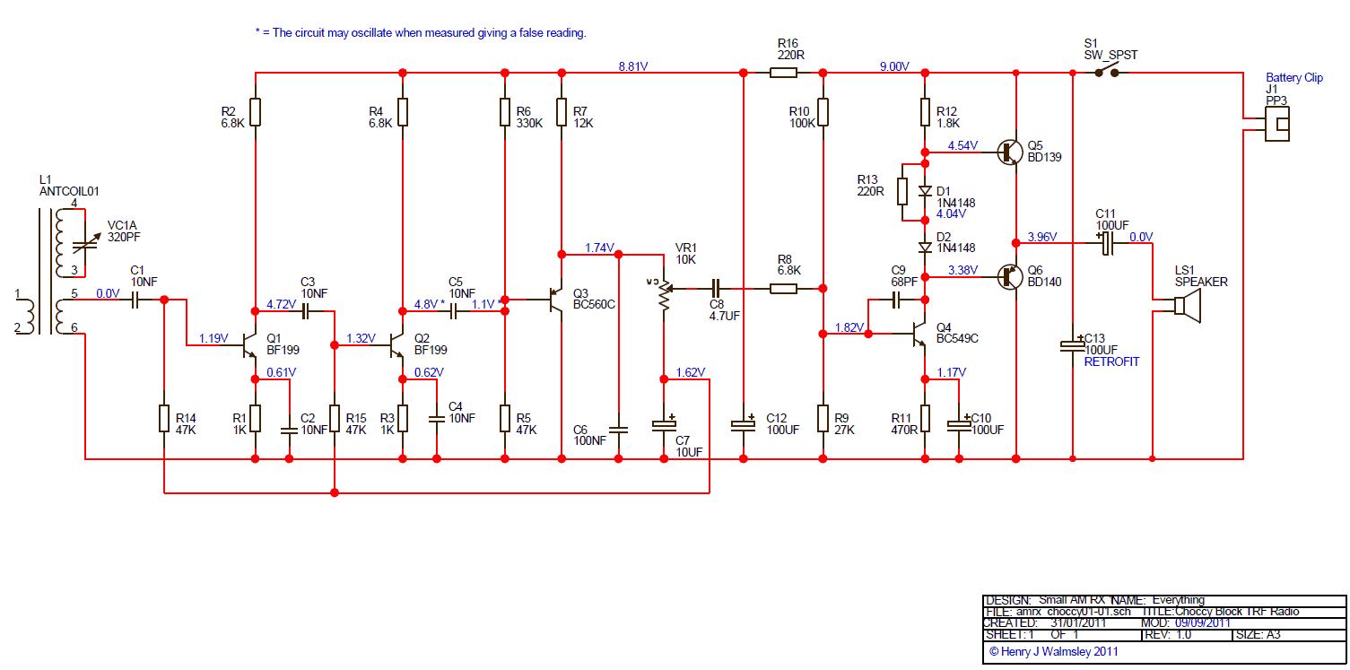
Am radio circuit diagram. On the other hand a circuit with narrow bandwidth suitable for audio is useful for selecting a station as explained next. It has 8 pins. As can be seen in the given circuit diagram the design is as simple as it can be just a couple of general purpose transistors and a few other passive components for configuring what looks like a nice little am radio receiver unit.
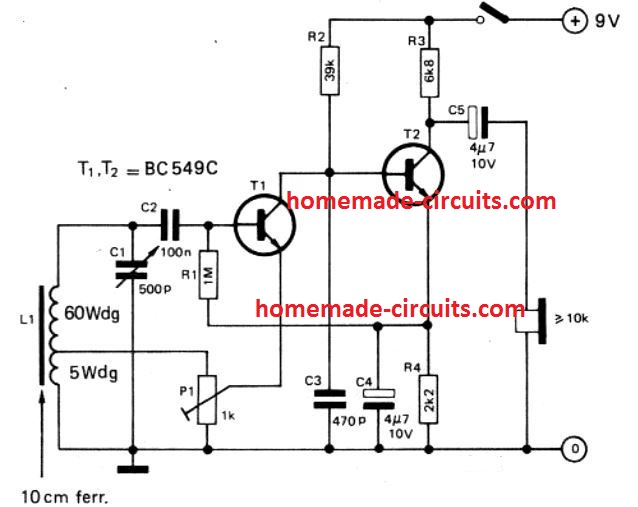
All general purpose transistors should work in this circuit you can use bc549 transistors for this circuit. Follows fcc regulations and still produces enough amplitude modulation. The schematic mentioned here is also a simple am radio circuit but it is not using a crystal it is using high gain preamplifier stage of transistor bc 549.
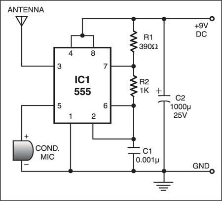
This is a low voltage audio power amplifier. A simple am transmitter circuit with diagram and schematic. This is the circuit diagram of the simplest single chip am radio.
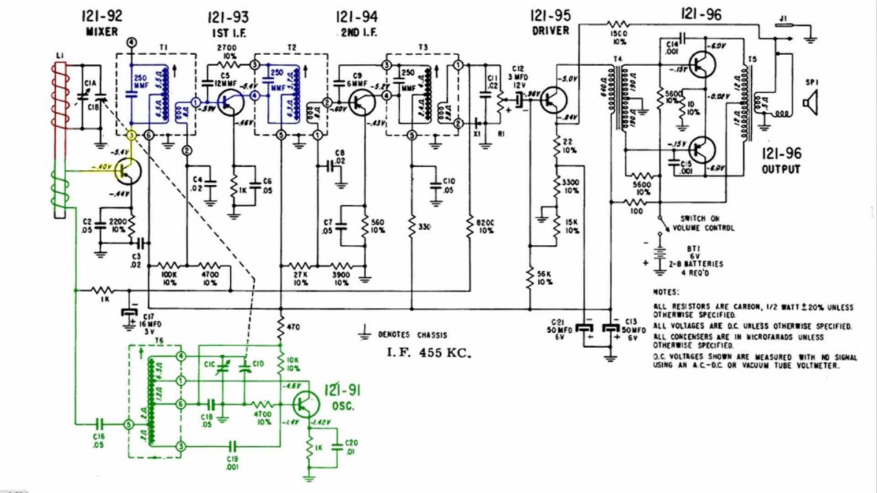
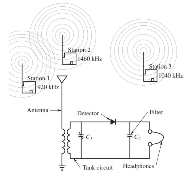
Simple am radio receiver this circuit is essentially an amplified crystal set. First mass produced transistor radio 1954. The overall block diagram of most am radio receivers is detailed.
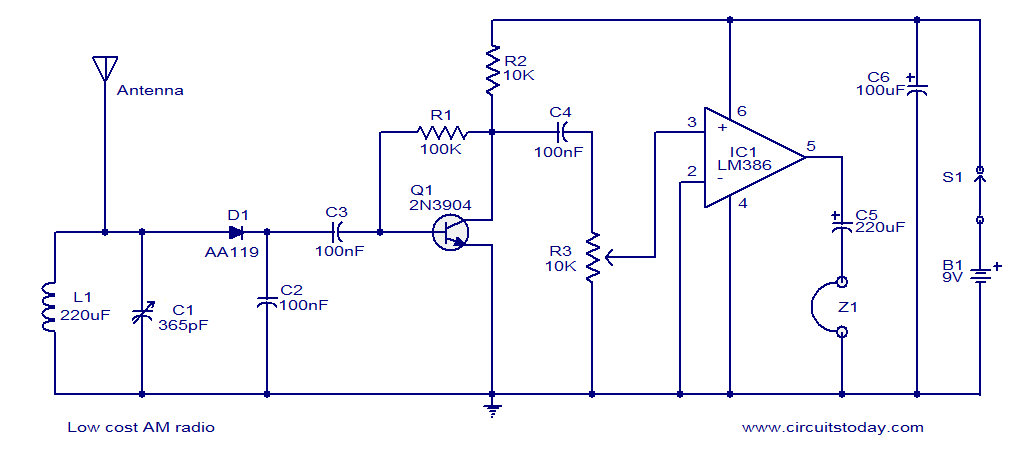
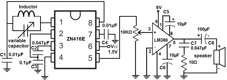
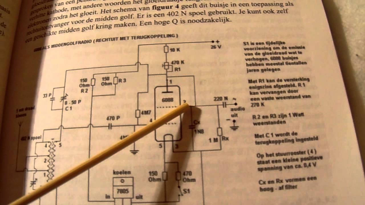
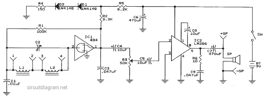
The transistor t1 works as a feedback regulated hf amplifier and. The inductor could be a standard am radio ferrite rod antenna while the tuning capacitor is a variable plastic dielectric gang intended for small am radios. It has an op amp internally which acts as an amplifier.
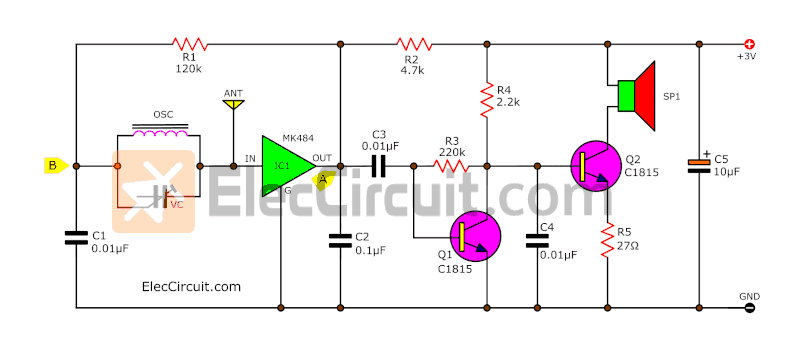
The non inverting pin is connected to the variable resistor of 10kohms. It uses only 2 transistors and few passive components which makes is very easy to be constructed. The fm radio circuit mainly consists of lm386 ic.
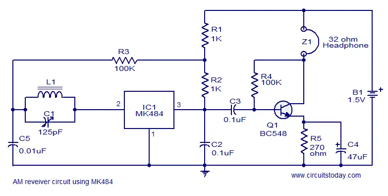
Inverting pin of the lm386 ic is connected to the ground. Although the circuit is very simple it functions very well without external antenna or ground connection. It is similar in principle to the zn414 radio ic which is now replaced by the mk484.
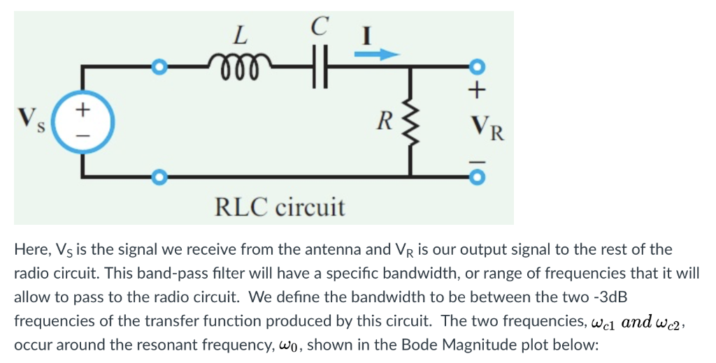
The circuit use a compact three transistor regenerative receiver with fixed feedback. A circuit with a narrower bandwidth than the range of audio say 1khz would attenuate or cut out the higher frequencies in audio and distort the output. The aerial tuned circuit feeds diode d1 which functions as the detector.
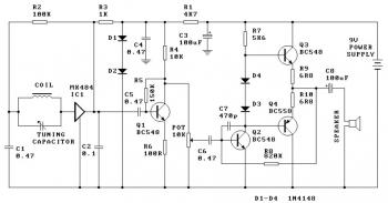
This two transistor am radio circuit is also called mini radio. For more crystal radio circuits simple one transistor radios and more advanced low transistor count radios. This is the circuit diagram of mini am radio receiver.
This am radio transmitter can transmit audiosound to your backyard. It operates at a supply voltage of 4 12 volts.
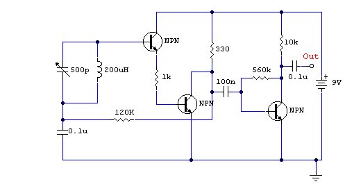
![]() Three Transistor Radio Circuit Diagram
Three Transistor Radio Circuit Diagram
 Am Radio Circuit Diagram Com Imagens
![]() Two Transistor Am Radio Receiver Circuit
Two Transistor Am Radio Receiver Circuit
![]() Two Transistor Radio 6 V Option
Two Transistor Radio 6 V Option
 Make A 1 5v Am Radio Radio Fm Radio Receiver Ham Radio
 Radio Circuits Blog Simple Am Radio Receiver
 Am Receiver Circuit
 Simple Am Receiver Circuit Diagram With Images Receiver Fm
 Mini Am Radio Receiver Circuit
![]() Three Transistor Radio Circuit Diagram
Three Transistor Radio Circuit Diagram
 Tn 8672 Am Receiver Circuit The Am Signal Can Be Received Using
Make An Am Radio Receiver With Three Transistors Circuit Diagram
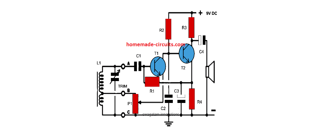 Simplest Am Radio Circuit Homemade Circuit Projects

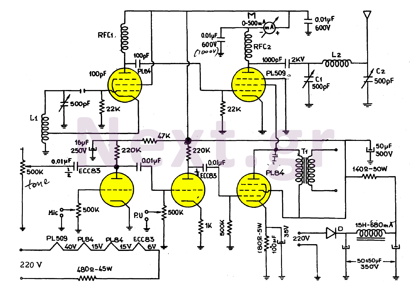
 Ka 5429 Am Radio Circuit Rf Circuits Nextgr Download Diagram
Two Transistor Am Radio Receiver Circuit Schematic Transistor
 Sw Converter For Am Radio Schematic Circuit Diagram
Simple Am Radio Receiver
![]() Simple Transistorized Am Radio Circuit Diagram Electronic
Simple Transistorized Am Radio Circuit Diagram Electronic
 Low Range Radio Transmitter Detailed Circuit Diagram Available

 Sw Converter For Digital Am Car Radio Schematic Circuit Diagram
 Mh 7821 Simple Am Radio Receiver Schematic Wiring

 Solved A Basic Am Radio Circuit Diagram Is Shown Below D
 Super Simple Mw Am Radio Circuit Hackaday Io
 Cd9088cb Am Fm Radio Kit On Ebay Circuit Diagram
 27mhz Superhet Am Receiver Dengan Gambar
 Hd 7643 Fm Schematics Schematic Wiring
 Simplest Am Radio Circuit Homemade Circuit Projects
 Signal Flow Transistor Am Radio Youtube

 Simple Am Radio Receiver Circuit With Earphone Eleccircuit
 Nr 9611 Am Radio Receiver Schematic Wiring

Am Receiver Circuit Using Ic
Superheterodyne Receiver With One Transistor
 1 Tube Am Radio Circuit From The 1920 S How To Make It Youtube
 Am Radio Receiver Circuit Showing The Main Electronic Components

 Radio Circuits Practical Analog Semiconductor Circuits

![]() Circuit Simple Am Radio Circuit Using Transistor
Circuit Simple Am Radio Circuit Using Transistor
 Am Radio Receiver Electronic Circuit Diagram
One Transistor Radio Circuit Diagram
 Frank Sumption S Frank S Box La1600 Am Radio Circuit Itc Voices
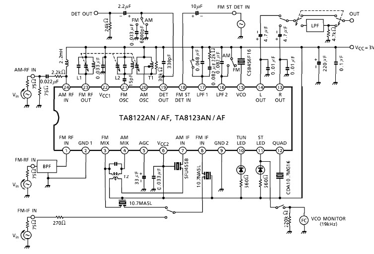
 Am Radio Fm If Stereo System Ic
 How To Build An Arduino Controlled Am Fm Sw Radio Projects
![]() Simple Two Transistors Am Transmitter Circuit
Simple Two Transistors Am Transmitter Circuit

 Am Radio Receiver Circuit Diagram Circuit Diagram Transistor
 Amazon Com Am Radio Circuit Using Ic Mk484 Unassembed Kit 4 5
![]() One Transistor Radio
One Transistor Radio
 Using Three Op Amp Simple Am Fm Radio Circuit
 What Is The Best And Simple Circuit Diagram For A Radio Receiver
 Simple Am Radio Receiver For Emergency Situations
 Hz 8556 Fm Schematics Download Diagram
6 Transistor Radio Schematic
 Amplitude Modulation Ppt Video Online Download
Radio Receivers Download Antivirus Timeline Pictures Posters

![]() Simple Am Radio Transmitter
Simple Am Radio Transmitter
Am Radio Circuit Page 3 Rf Circuits Next Gr
 Yo3dac Homebrew Rf Circuit Design Ideas
 Radio Transmitter And Receiver Working Block Diagram
![]() Am Transmitter Electronics Project
Am Transmitter Electronics Project


9v Fm Radio Transmitter Electronic Schematic Diagram
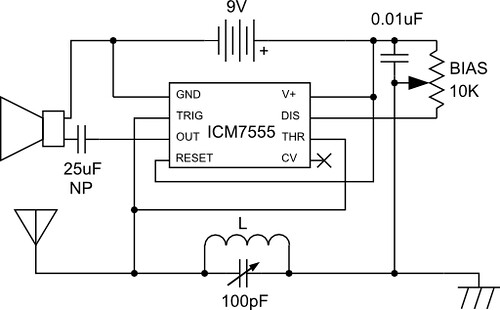 555 Am Radio
 Ac 8119 Tuner Circuit Diagram Likewise Fm Radio Receiver Circuit

 Cxa1019 Fm Radio Circuit Diagram Electronic Boy For You
 Yo3dac Homebrew Rf Circuit Design Ideas

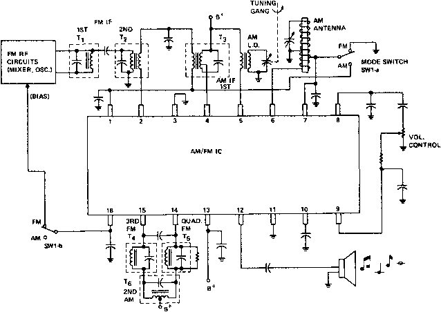 Figure 1 From A Single Chip Am Fm Integrated Circuit Radio
 Reflex Receiver Wikipedia

1590145192000000
 A Simple Am Modulator

 Useful Components Breadboard Transistor Radio
 Radio Am And Fm
